Germany
 Italy
Italy USA
USA South Korea
 UK
UK India
India France
 China
China Japan
JapanHeader
Friday, 05 February 2021 15:49
CGTech Announces 3DLive™ GDML Interface for VERICUT® Software
CGTech Announces 3DLive™ GDML Interface for VERICUT® Software
Irvine, CA – CGTech has announced that its VERICUT software can now read in Geometry Description Markup Language (GDML) files with a new 3DLive Interface. GDML is an application independent geometry description format based on XML.
3DLive is available in MachiningCloud for products that require kinematics such as Machine Tools and Workholding devices. MachiningCloud has traditionally been known for the ability to provide 3D models of cutting tools for use in VERICUT and other related CAD/CAM and simulation software. DMG MORI, HAAS Automation, Mazak, Kennametal and KURT Workholding are among the first to supply GDML machine tool, driven turret units and fixture models to MachiningCloud.
VERICUT is the first software of its kind to support the import of 3DLive files for use in verifying, simulating and optimizing NC programs. This enhancement provides VERICUT users the ability to read in 3DLive data for CNC machines, workholding fixtures and cutting tool holders for use in simulations. This eliminates having to measure and model the components by traditional means or request 3D models from the machine tool builder.
“What has traditionally been a challenging and time-consuming procedure to obtain machine specific information and manually build digital twin machines, can now be done quickly and easily in VERICUT using the new 3DLive interface to read information-rich geometry data,” says Gene Granata, VERICUT Product Manager.
The 3DLive catalog in MachiningCloud currently contains over 8,700 products. 3DLive files contain kinematics, travel limits, minimum and maximum feed rates, initial machine location and 3D geometry colors in a single file format. This data can be read into VERICUT in a matter of seconds. 3DLive fixtures can be utilized to exactly represent the workholding setup in a VERICUT simulation. These fixture models sometimes contain axis movement (I.e. vise models that open/close). Additionally, 3DLive tool assembly holders can be read into VERICUT’s Tool Manager.
About CGTech
CGTech’s VERICUT® software is the standard for CNC simulation, verification, optimization, analysis, and additive manufacturing. CGTech also offers programming and simulation software for composites automated fiber-placement, tape-laying, and drilling/fastening CNC machines. VERICUT software is used by companies of different sizes in all industries. Established in 1988, and headquartered in Irvine, California; CGTech has offices worldwide. For more information: visit the CGTech website at cgtech.co.uk, call (949) 753-1050, or email info@CGTech.com
About MachiningCloud
MachiningCloud is dedicated to leading a digital shift within the discrete manufacturing industry to deliver a new level of operational efficiency. Cloud-based applications, resources, services, knowledge, and digital product data from the world’s leading manufacturers of cutting tools, machine tools, workholding and specialty products are providing efficiency improvements by facilitating the flow of data to and from today’s data intensive shop-floor. For more information: visit www.machiningcloud.com, or call (805) 437-4171.
# # #
EDITOR’S NOTE: Electronic image attached – 3D_Live-HAAS_UMC750-transl_window.png
CGTech, VERICUT, and OptiPath are registered trademarks of CGTech.
AUTO-DIFF and X-Caliper are trademarks of CGTech.
Published in
Press Releases 2021
Tuesday, 14 July 2020 12:57
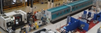
CGTech provides the FORCE behind the nuclear science
Published in
Aerospace

Thursday, 04 June 2020 13:48
VERICUT Version 9 fully optimized for maximum efficiency
The latest version of VERICUT CNC simulation, verification and optimization software was released earlier this year but continues to be improved and enhanced with additional incremental releases, which maintained users are automatically.
 VERICUT 9 is a game changer for verifying NC programs, with sharper displays, clearer views of the cutting process and better utilization of the system resources, making it easier to spot problems and imperfections in machined parts. It runs a lot of operations multi-thread and really makes use of GPUs that previous versions didn’t do.
The biggest improvement visible to the end user in VERICUT 9 is the new, more flexible and all open GL viewing environment. Users get optimal performance running simulations in a single view or multiple views, seamlessly switching between Workpiece, Machine, or Profile views, or view layouts for optimal viewing.
Users no longer have to use individual views to perform each operation – run a machine simulation, cut a section while it’s running or use X-Caliper and AUTO-DIFF all in the same window. All this runs smoother and quicker than in previous versions and streamlines the verification effort to increase productivity.
With other enhancements users can automate many processes with just a click of button. Check cutting limits, check spindle direction, check coolant, check syntax, check tools – all these can be pre-set, saved in a master template and VERICUT will run the checks automatically. These are all things that will help even the most experienced VERICUT users to use the software more effectively.
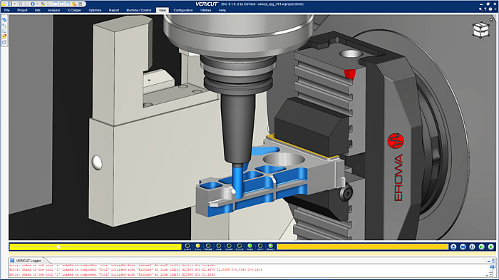
Finding and fixing problems is now quicker than ever before. Program preview quickly runs through the program without actually cutting the part, identifying machine crashes, fixture crashes and travel limit errors Issues are identified in the VERICUT logger and clicking the error it takes you directly to the block in the NC program where the error occurs where changes can be made. Using the new Restart function there is no need to verify from the start. Just verify the NC code from the line where changes have been made. This will be a huge benefit anyone verifying large NC programs.
 As well as simulation and verification enhancements, Air-Cuts only optimization allows users to optimize tool motions that are not in contact with material with. This is included in Verification, it’s easy to use and it runs while simulating. For more advanced optimization, the VERICUT Force module comes with enhanced charts for analysing cutting conditions, chip thickness and tool deflection.
“The software is constantly improving making things quicker and easier for all users” Says Gavin Powell, CGTech Ltd Technical Director. “The aim is to help our customers be more efficient, more competitive and therefore more profitable.”
Published in
Press Releases 2020
Thursday, 04 June 2020 13:39
Achieving process optimization through simulation
 Process optimization links all the machining operations end-to-end to evaluate and improve the entire manufacturing process. Each step along the way, through engineering, design, CAM programming and machining and up to the final quality and inspection phase, can and should be optimized. Simulation ensures programs are error free and all operations work together as intended, but optimization ensures the whole process is operating as efficiently as possible to save time and money.
As machining gets more complex and customers expect more for less there is room for improvement in any manufacturing process. These improvements, which are not just about reducing costs, might include reduced NC program runtimes, increased throughput, making parts cheaper or getting a product from start to finish and out to market faster.
There are some very significant warning signs that will indicate when process optimization is clearly a must in a manufacturing business – missing delivery dates? Losing out on bids or not as competitive as rivals? Lost contracts and unsatisfied customers? Or declining profits?
Every level of the manufacturing process that a job goes through requires careful planning and communication and the aim of manufacturing is to make it through each step as quickly and efficiently as possible, with the least cost incurred.
In a typical manufacturing workflow VERICUT resides between CAM programming and machine set up.
Manufacturing workflow with VERICUT
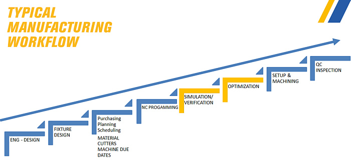 CAM programmers know that modern machines move so fast it’s pretty much impossible to stop them before a crash occurs. VERICUT CNC simulation and verification software does a superior job at finding problems lurking in NC programs and warning of unexpected machine behaviour, even those occurring between multiple setups. It lets programmers resolve these issues before they reach the shop floor, crash the machine and waste valuable machine time.
With VERICUT the shopfloor can be confident that programs will run correctly. Verification will show if there are any errors or any areas that can’t be reached by the machine or the tools due to fixturing interference. Machinists don’t have to worry about crashes and they don’t have to waste time proving out because it’s already been done between the VERICUT and programming stages.
Having access to the free VERICUT reviewer at the machine tool to check the simulation against reality at anytime is a huge benefit to both shop floor and programmers as it avoids the “what happens next” disturbances during one off or first off production.
There’s also a positive ripple effect for other departments that coordinate with programming. Engineering and design can learn through verification if parts can be manufactured or if changes need to be made before metal cutting. Planning and scheduling will have more accurate cycle times and they won’t have to schedule prove-out times on the machines. The quality control and inspection team can expect higher levels of conformance and fewer issues which makes it easier to approve parts and get them delivered.
These are all areas where VERICUT is helping save time and money.
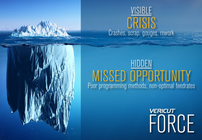
Silent Killers of NC manufacturing
But there are also the hidden issues, inefficiencies and missed opportunities to optimize processes that erode profit margins. Things like poor cutting methods, non-optimal feedrates in new and existing NC programs, over or under utilizing cutters and/or machine tools, all of which can be draining money with every part made. Some companies work really hard and very diligently optimizing programs but there are opportunities and savings to be had for all machine shops.
This is where Force and Force analysis charts come in.
Force Analysis and Charts
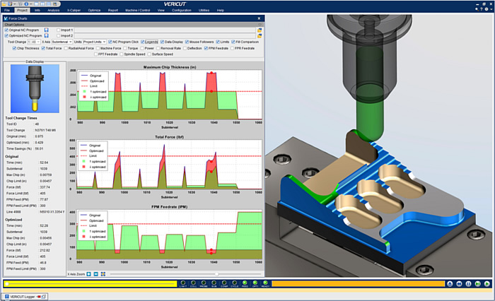 VERICUT Force recalculates feedrates to maintain ideal constant chip thickness while simultaneously reducing feedrates when needed to maintain safe cutting forces and spindle power, and it does this for each tool. Force is based on calculations and proven cutting data that’s been gathered from tooling manufacturers, material specifications and dyno testing.
It uses very specific cutting parameters, takes into consideration what kind of material is being used, as well as tool type and geometry. It couples this with the cutting conditions that VERICUT collects to give the best data that can be used to analyse and optimize the NC program.
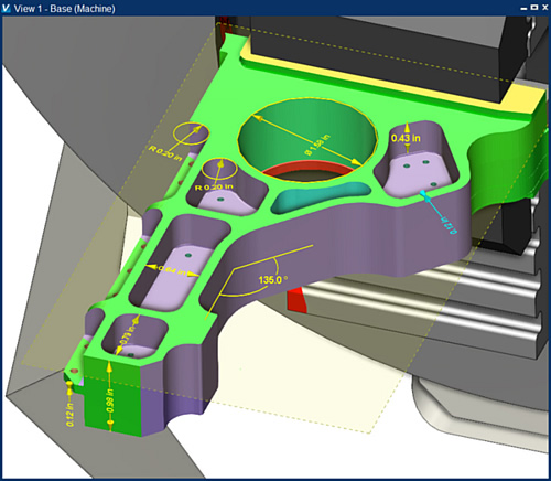
Force charts visualize what’s happening during the machining process and expose areas of opportunity that exist in each NC program, such as erratic chip thickness, chip thinning and inefficient CAM paths that can all be resolved by optimizing feedrates. The charts also show areas of concern, for instance where the force exceeds what the tool capable of, such as excessive cutting conditions or potential for chatter, broken/chipped cutters or damage to part of the machine. In these instances VERICUT Force will lower the federate to keep the force under the limit that of the tools capability.
The impact of optimizing is dramatic, including reduced machining time and longer tool life, which will help the shopfloor by giving more machine capacity and maybe even postponing the purchase a new expensive machine. There will be less post machine clean up because produced parts will be better quality saving even more time per part. Programmers are going to benefit from having correct speeds and feeds information to achieve consistent machining results. All these positives reach all the way back to the quoting and estimating and mean manufacturers can be more aggressive and competitive with schedules and bids.
Simulating, verifying and optimizing simultaneously with VERICUT Force equates to a cumulative effect on process optimization resulting in significant time and money savings.
Published in
Press Releases 2020
Tuesday, 10 March 2020 08:57
Steelville Manufacturing
Steelville Manufacturing Co. produced more than 8,500 discrete part numbers last year, most in lot sizes of 32 pieces or less, with 80% going directly to aerospace OEMs or their Tier-One suppliers. As engineering VP John Bell puts it, there’s no room for error. Installing Vericut toolpath simulation software from CGTech has helped the Steelville, Missouri, shop avoid crashes, reduce setup times and cut cycle times on its machining centers and lathes.
Published in
Aerospace